Need some help boys.
Got EFIE wired up today. Sorta.
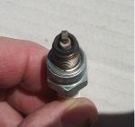
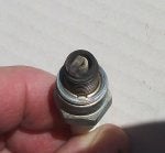
There are 4 wires to O2. (2) white which I believe are HEATER circuit, a black which is positive signal (to ECU) and a grey which I THINK is just a ground. But it is a ground that goes back to the ECU.
I intercepted the Black (positive signal wire) with EFIE and set it up so voltage that passed through it was reduce by 0.250 volts. Used multimeter to test I verified that it worked on the bench and once in the bike. I tested the positive signal wire on both sides of the device and all was good.
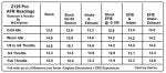
Fired up the bike and it threw a code. I thought maybe the modified signal was out of range. AFR was whacky. Started high almost 15 then dropped to 12-13. I adjusted the device to drop signal by 0.150 volts and went for a ride. AFRs were mixed. Giving it more throttle the AFRs seemed lower. with the throttle cracked they were 14.2-15. This behavior was similar to running without the O2. Coming off throttle idle would end up around 13 afr then creep up to 14.6ish after maybe 15 seconds. Almost like the system was fighting with itself. Maybe idle is open loop and previously learned trims were coming into play.
After the ride I pulled the code - #67 for O2 heater element. Strange. I checked resistance through the 2 white wires (running to the O2) and got 18 ohms which per manual is in spec. I checked for voltage feeding the heater circuit at the O2 harness and had battery voltage. So I'm not sure why I'm getting heater circuit code. The manual says next step is check continuity to the ECU and if that is good then get a new ecu lol. I think it must just be a fluke code because I didn't mess with ECU or harness wiring. I tapped into O2 harness only.
I was reading 1.2 - 1.35 volts on the positive O2 signal wire before modification, this was giving me AFR readings around 14.2. This is my first time playing with narrow band O2s so I don't know what kind of voltage to expect. I'm measuring positive signal to ground. This may be an important detail. The manual, when testing the O2 positive signal wire voltage, has you connect to the grey wire (the mystery maybe a ground that definitely goes back to ECU) and not just any ground. Not sure if this matters. For more understanding of the ramblings in this paragraph crack open that manual to section 3-62. It is for diagnosing O2 sensor performance. It says connect positive lead of voltmeter to BLACK (check) and negative lead to GREY (I used chassis ground). It then goes on:
(Rich) DC 0.8 V or more
(Lean) DC 0.24 V or less
I'm getting 1.3 V at 14:1... so wtf?
Maybe the negative side actually has some positive voltage that would lower my reading when measuring across the black and grey wires. In any event a 0.250 V drop considering the range of 0.8 - 0.24 may be too much.
Thoughts?
Tonight I disconnected the ECU hoping overnight all fuel trims will be forgotten. Not sure if I should zero out the EFIE and ride it until the CEL clears or just ride for a while with the 0.150 offset.
.
Questions are just really trying to learn here more than I'm helping you I'm sure , But maybe something in one of my questions might trigger something for you ?
Dont answer anything that is waaaay of base .. and that answer my question
")
[[and a grey which I THINK is just a ground. But it is a ground that goes back to the ECU.]
[[ (the mystery maybe a ground that definitely goes back to ECU) and not just any ground.]
[[has you connect to the grey wire (the mystery maybe a ground that definitely goes back to ECU) and not just any ground. Not sure if this matters. For more understanding of the ramblings in this paragraph crack open that manual to section 3-62. It is for diagnosing O2 sensor performance. It says connect positive lead of voltmeter to BLACK (check) and negative lead to GREY (I used chassis ground). It then goes on:]]
.
The gray does go to the ECU, (3-63)(page 135)
.
.
[[with EFIE and set it up so voltage that passed through it was reduce by 0.250 volts. Used multimeter to test]]
.
Reduced? you mean you set it to 250 mv like the grom guys did?
.
.
[[I thought maybe the modified signal was out of range]]
.
from grom guys ... If we look at a narrow band o2 sensor voltage chart you can see a ~250mv offset will make the switching poing around an afr of ~ 13.3-13.5:1. You can not go much above 350mv decrease as you get to the point of the ecu always seeing 0 volts and this will throw a CEL and not be able to properly lean out and tune to how it wants.
.
.
[[Fired up the bike and it threw a code.]] Above statement (from grom guys)
.
Is it because you removed the 02 to test on the bench ?
have we ever conformed when CEL comes on after disturbing the 02' that it is for 02 #33 code or for the #67 heater code
.
.
[[Coming off throttle idle would end up around 13 afr then creep up to 14.6ish after maybe 15 seconds. Almost like the system was fighting with itself. Maybe idle is open loop and previously learned trims were coming into play.]]
.
Like you were thinking WOT would do .. but why would it creep
Did you get a WOT reading.
.
.
[[I'm getting 1.3 V at 14:1... so wtf?]]
.
because the Gray wire is not going to the ECU
.
.
did you take the EFIE gray wire to the 02
and the EFIE green wire to the ECU
Like the grom guys did ?
.
YOU GOT THIS :wink2: